")
")
")
")


Noise and concentricity tests of gears

Noise and concentricity tests of gears
Test speeds and short evaluation times allow 100% series control in production. When rolling (or toothing), the gearing creates typical, measurable behavior patterns that are detected by acoustic and / or geometric sensors and evaluated by test programs using computing methods. The results provide information about the composition of the error signal and thus enable the exact cause of the error to be identified (nicks, Center distance, Radial run-out , Tooth to tooth composite deviation, Total composite deviation, Theoretical two balls measurement). It is also possible to draw conclusions about previous work steps in which the geometry of the test object relates to incorrect or incorrectly set clamping devices.

| Double-flank testing | Single-flank test | |||
|---|---|---|---|---|
| Geometrical test | Noise test | TAC-Test (Torsional-Acceleration-Test) |
TE-Test (Transmission Error Test) |
|
| Characteristics |
|
|
|
|
| Accuracy, Resolution & Repeatability |
|
|
|
|
| Test characteristics |
|
|
|
|
| Sensors |
|
|
|
|
| Testing system | LiTW testing program | Discom Rotas ZP | Discom Rotas TAS | Discom Rotas TES |
A gear test can be done in a variety of ways, e.g. by analyzing the noise behavior or mechanically, e.g. by means of a center distance measurement, determination of the rotational acceleration, or by a target / actual comparison of the theoretical and actual position of a gear pair) or by a combination of acoustic and mechanical test methods. The gear testing is based on single-flank and double-flank rolling.
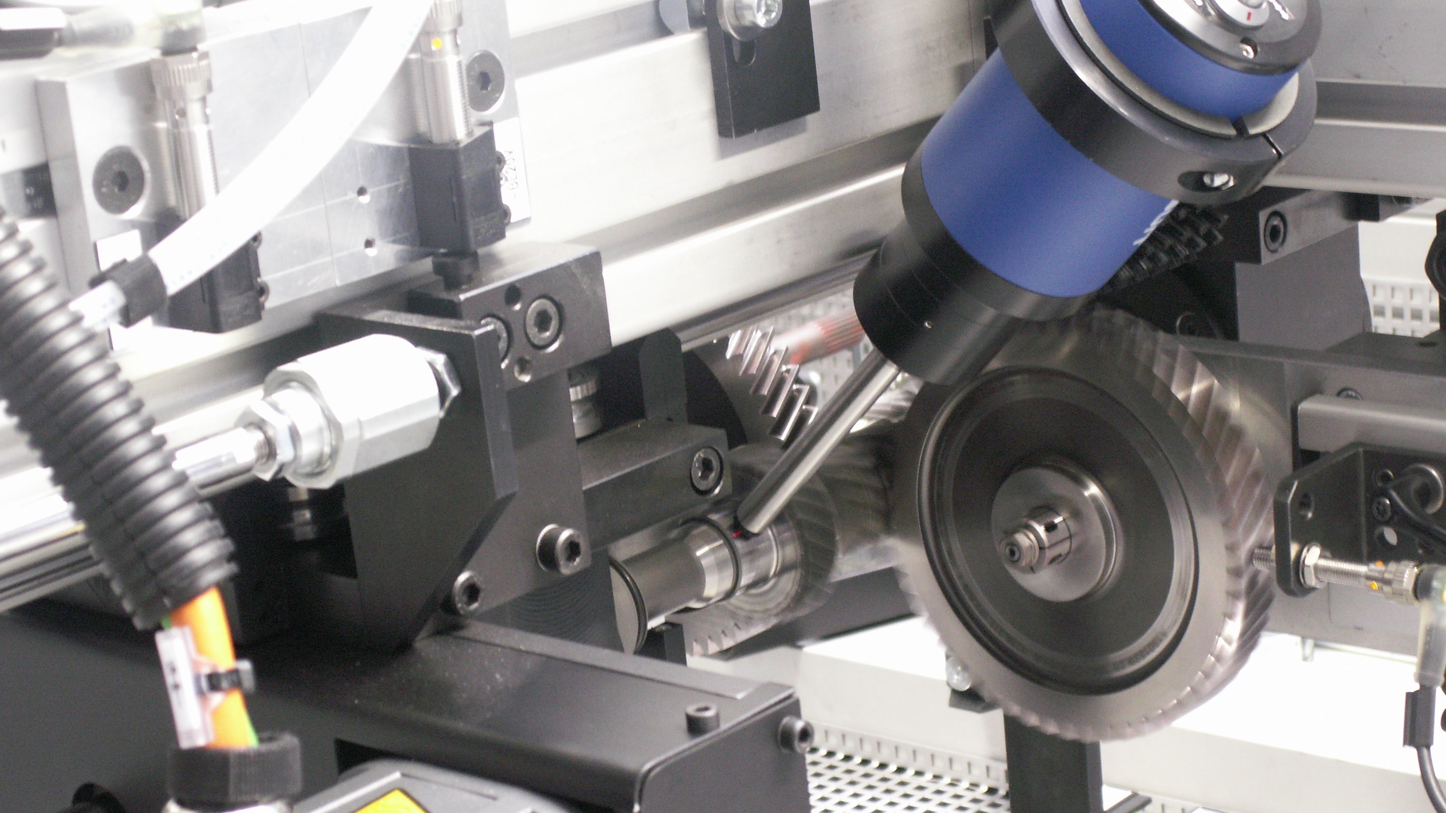
Double-Flank-Gear-Test (Geometrical / Noise Test)
The specimen and the master gear have a dynamic center distance to each other, in which the two components are in double-flank contact. The specimen is driven and the master gear moves with a defined spring pressure on two-flank contact with the specimen. Due to geometrical errors or damages to the test object, the test slide moves with the master gear by the length ∆a.


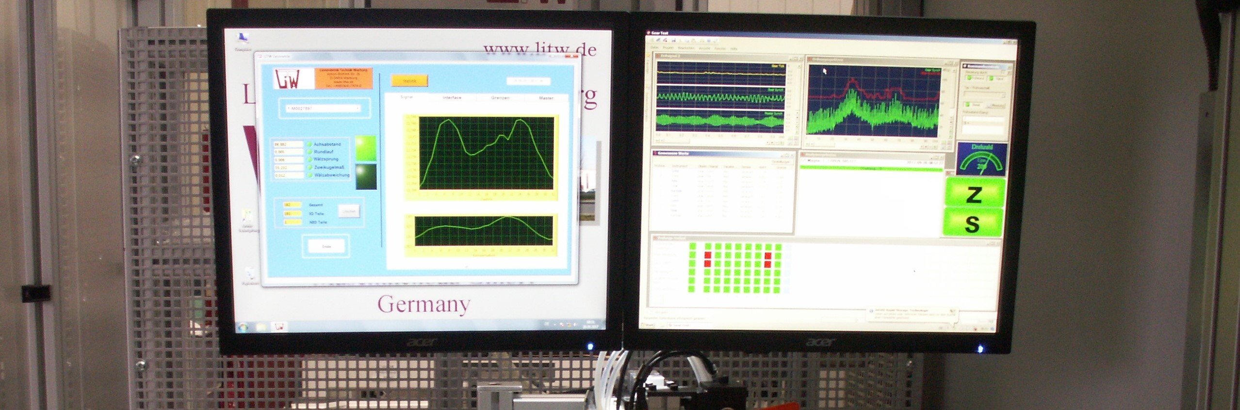
Evaluation of the gear test

Noise test system for shafts and wheels


Single-Flank-Test (TAC testing)

The TAC-Sensor is mounted on the spindle shaft of the specimen or of the Master Gear for the test. This sensor measures the non-uniformity of rotation. This irregularity can be caused by various errors in the toothing.
e.g.: radial run-out, whobble, any kind of mistakes in contact pattern, etc.


TE-test (Transmission Error)


Optical surface inspection


Marking and identification systems


